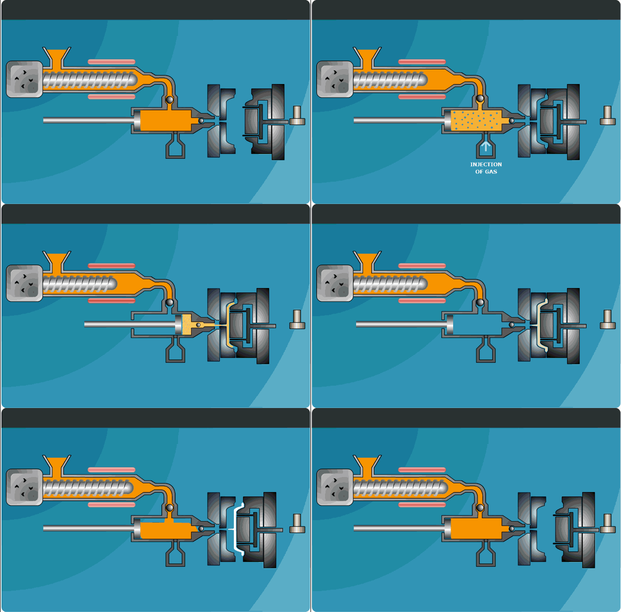
In the world of injection molding, cavity pressure is like an invisible "invisible pusher"—it determines whether the plastic can fill every corner of the mold and affects the dimensional accuracy and surface quality of the part. Imagine the plastic melt in the mold is like a crowd squeezing onto a subway: too little pressure will cause "loose gaps," and too much pressure will cause "squeezing deformation." Today, let’s talk about how to use mathematical magic to calculate this critical "squeezing force" and make the injection molding process more precise!
Cavity pressure refers to the pressure exerted by the plastic melt on the inner wall of the mold cavity during the injection molding process, measured in megapascals (MPa). It is like the "crowd density" at a subway security checkpoint, directly reflecting the "crowding degree" of melt filling.
Core Formula:\(\text{Cavity Pressure} = \text{Injection Pressure} \times \text{Pressure Loss Coefficient}\)Simply put, the "total thrust" applied by the injection molding machine (injection pressure) is "discounted" (pressure loss) after passing through "layers of checkpoints" such as runners and gates, and the pressure that actually reaches the cavity is the result.
Runner Length and Diameter: The longer and smaller the diameter of the runner, the greater the pressure loss (similar to how water pressure decreases with longer water pipes).
Gate Size: Small gates (such as submarine gates) significantly increase pressure loss, possibly reducing cavity pressure by more than 30%.
Plastic Viscosity: High-viscosity materials (such as PC) are like "sticky syrup" in injection molding and require higher cavity pressure to flow.
Data Source: Check the injection molding machine’s dashboard or refer to material supplier recommendations (e.g., ABS injection pressure is typically 80-120 MPa).
Example: An injection molding machine producing PP parts has a set injection pressure of 100 MPa.
Formula:\(\text{Pressure Loss Coefficient} = 0.5^{\text{Runner Length/10 cm}} \times \text{Gate Correction Coefficient}\)
Influence of Runner Length: For every 10 cm of runner length, multiply the coefficient by 0.5 (e.g., if the runner is 20 cm long, the coefficient = 0.5 × 0.5 = 0.25).
Gate Correction: Large gates (such as fan gates) have a coefficient of 0.8, while small gates (such as pin gates) have a coefficient of 0.6.
Example: A runner length of 15 cm (calculated as 20 cm), with a pin gate, the pressure loss coefficient = 0.5² × 0.6 = 0.15.
Formula:\(\text{Cavity Pressure} = 100 \text{ MPa} \times 0.15 = 15 \text{ MPa}\)Analogy: It is like pushing toothpaste with a force of 100 Newtons—after passing through a narrow tube opening, the actual force applied to the toothpaste is only 15 Newtons.
To make it easy to remember, here’s a calculation mnemonic:
First, check the injection pressure; second, observe the length and thinness of the runner; Third, calculate the discount from the gate; fourth, multiply by the coefficient to get the pressure.
Example Verification:
Injection pressure of 120 MPa, runner length of 30 cm (calculated as 30 cm, coefficient = 0.5³ = 0.125), fan gate (coefficient = 0.8).
Cavity pressure = 120 × 0.125 × 0.8 = 12 MPa.
Problem: The plastic fails to fill the mold, resulting in defects such as "short shots" and "sink marks," increasing the scrap rate in injection molding.
Case Study: A mobile phone case mold had insufficient cavity pressure (measured at 10 MPa vs. required 20 MPa), causing frequent short shots in the button area, with a rework rate as high as 30%.
Problem: The high pressure forces the mold open, creating "flash" and even damaging the mold (such as deformed guide pillars).
Data: When cavity pressure exceeds 80 MPa, mold wear speed increases by 50%!
Principle: Install micro pressure sensors on the mold cavity wall to display real-time pressure curves.
Advantage: More accurate than formula calculations, capable of early warning of pressure anomalies (such as sudden drops possibly indicating gate blockages).
Normal Filling: Pressure rapidly rises to a peak and then gradually decreases (e.g., ABS filling peak pressure is 50 MPa, holding pressure at 30 MPa).
Abnormal Signals: Pressure fluctuations exceeding ±10% may indicate material degradation or mold wear.
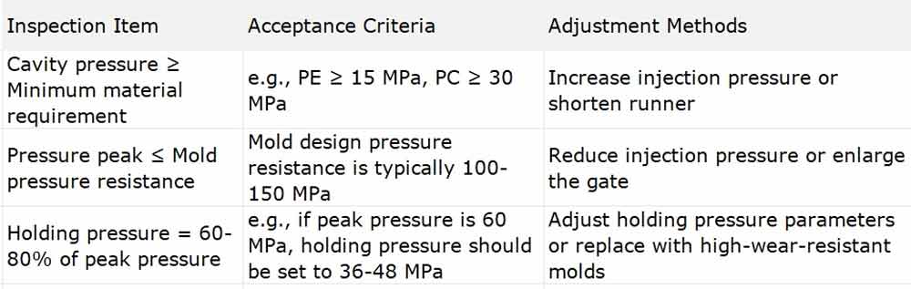
Calculating cavity pressure is like conducting "strength training" for the injection molding process—too little strength fails to achieve results, while too much strength causes injury. Mastering the formula method of "finding total pressure and calculating loss," combined with real-time monitoring using pressure sensors, allows the plastic melt to fill every detail in the mold with the right "squeezing force." The next time you debug an injection molding machine, remember to use this mathematical magic to crack the pressure code and take part quality to the next level!


