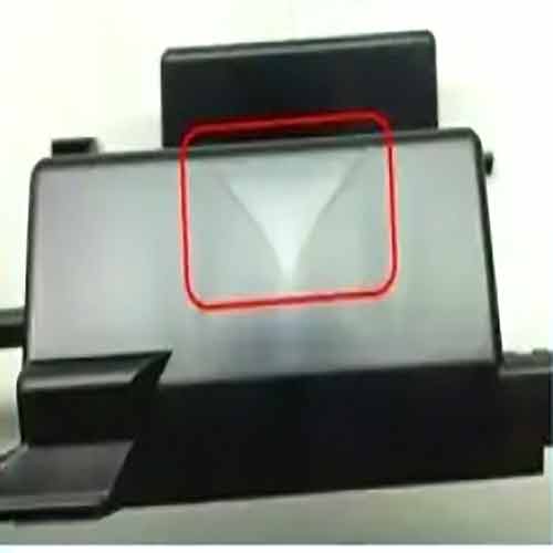
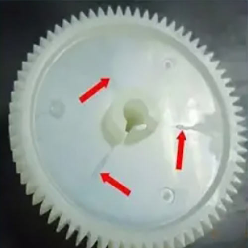
In injection molding, weld lines are linear defects formed when two or more streams of molten plastic fail to fully fuse upon meeting in the mold cavity. These defects not only compromise a part’s appearance (e.g., reduced surface gloss, sink marks) but can also weaken mechanical properties (strength may decrease by over 30%), creating structural vulnerabilities. This article analyzes the formation mechanism of weld lines and provides systematic prevention strategies and practical methods.
Weld lines typically occur in the following scenarios:
Multi-Gate Design: Melt streams from multiple gates meet in the cavity, such as in three-plate molds or hot runner systems.
Structural Obstructions: Features like holes, ribs, or bosses force the melt to divide and rejoin. For example, the spokes of a gear cause melt to flow around the hub and converge.
Long-Flow Paths: Melt cools as it travels through complex or lengthy channels, leading to premature solidification at the confluence interface and insufficient fusion.
Melt Temperature and Flowability: Low temperatures increase melt viscosity at the interface, hindering fusion. For instance, when the melt temperature of polypropylene (PP) drops below 200°C, weld line strength decreases by approximately 25%.
Mold Temperature: A lower mold temperature accelerates melt cooling, reducing molecular diffusion time at the interface. Tests show that increasing mold temperature from 50°C to 80°C can improve impact strength at weld lines by 18% (ISO 179 standard).
Injection Speed and Pressure: High-speed injection may cause turbulent flow and oxide film formation on the melt surface, while low speed can lead to premature solidification.
Material Properties: High-viscosity materials (e.g., polycarbonate, PC) or reinforced materials (e.g., glass fiber-filled nylon) are more prone to weld lines due to higher flow resistance and difficult interface fusion.
Minimize Gate Quantity: Prioritize single-gate designs (e.g., central gates) to avoid multi-stream confluence. For example, changing a car dashboard part from four-point gates to a single hot runner gate reduced weld lines by 70%.
Optimize Gate Location and Orientation:
Ensure a confluence angle ≥135°; larger angles reduce melt impact and improve fusion.
Use CAE tools like Moldflow to simulate melt flow and position confluence points in thick-walled areas or non-visible surfaces.
Use Fan or Submarine Gates: Fan gates reduce melt jetting and turbulence, while submarine gates hide weld lines within the part.
Shorten Runner Length: Long runners cause significant temperature drop. Maintain the main runner length below 150mm and adjust the sub-runner diameter by material (e.g., φ6–8mm for ABS).
Add Venting Grooves: Install venting grooves (0.02–0.05mm deep, 5–10mm wide) at melt confluence points (e.g., cavity ends) to exhaust air and prevent trapped gas from exacerbating weld lines.
Avoid Sharp Corners and Sudden Wall Thickness Changes: Sharp corners (e.g., right angles) disrupt melt flow, while sudden thickness changes cause stagnation. Use rounded transitions (radius ≥0.5mm) and gradual thickness changes (transition length ≥3× thickness difference).
Simplify Unnecessary Holes and Ribs: Reduce 分流次数 by simplifying designs in non-critical areas, such as replacing dense ribs with a single thick rib.
Increase Melt Temperature: Raising temperature within material limits (e.g., PC from 280°C to 300°C) can improve weld line strength by ~8% per 10°C increase. Avoid overheating (e.g., PVC degrades above 200°C).
Raise Mold Temperature: Set mold temperature at 60–90°C for crystalline plastics (e.g., PE, PP) and 40–70°C for amorphous plastics (e.g., PS, ABS) to prolong melt flow and promote fusion.
Choose low-viscosity grades for high-appearance parts. For example, high-flow ABS (e.g., Chi Mei PA-718) improves weld line strength by 20% compared to standard grades (PA-757).
Avoid high-filled materials (e.g., glass fiber content >40%). If necessary, use short fibers or surface-coupled reinforced materials to improve flowability.
Add 3%–5% compatibilizers (e.g., maleic anhydride-grafted ABS) to polymer blends (e.g., PC/ABS) to reduce interfacial tension and improve weld line compatibility, increasing tensile strength recovery from 65% to 85%.
Visual Inspection: Use a gloss meter to measure gloss differences (allowable difference ≤10GU) between weld lines and normal surfaces.
Mechanical Testing: Compare tensile or impact strength between weld line areas and the base material, requiring a strength retention rate ≥85%.
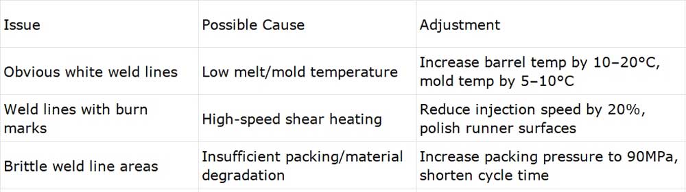
Background: An ABS appliance panel with two side gates had visible weld lines on the aesthetic surface, causing a 15GU gloss difference and 22% strength reduction.
Solutions:
Mold Modification: Switched to a single hot runner central gate, eliminating multi-stream confluence.
Process Adjustment: Raised melt temperature from 230°C to 245°C, mold temperature from 50°C to 65°C, and packing pressure from 60MPa to 80MPa.
Results: Weld lines disappeared completely, gloss uniformity met standards, and tensile strength recovered to base material levels.
Preventing weld lines requires a full-process approach covering "mold design–material selection–process tuning." By minimizing melt diversion, optimizing temperature/pressure parameters, enhancing interface fusion, and using CAE simulation for risk prediction, weld line occurrence can be significantly reduced. For high-demand parts, surface treatments (e.g., painting, plating) or structural designs (e.g., hiding weld lines in assembly areas) can further mitigate defects. Mastering these strategies ensures both aesthetic and functional excellence in injection-molded parts.


