
How to Avoid Flash in Injection Molding?
How to Avoid Flash in Injection Molding?
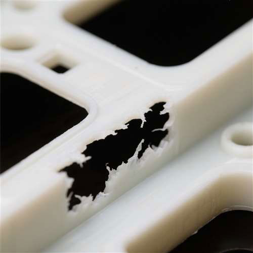
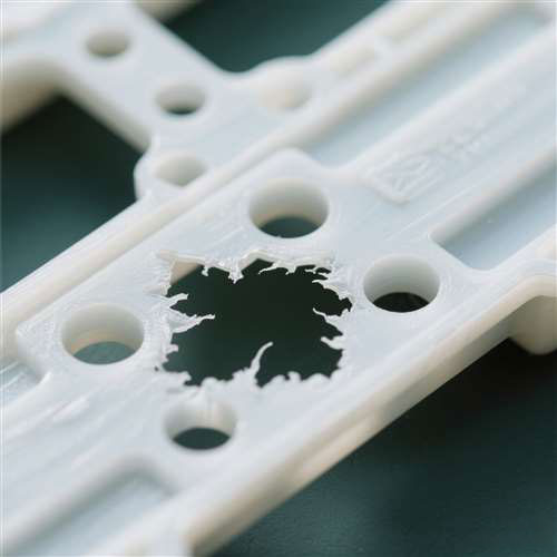
Issue: If the injection molding machine’s clamping force is insufficient to counteract the injection pressure, mold halves may separate slightly, creating gaps for plastic to escape.
Example: For a mold with a projected area of 100 cm² and injection pressure of 100 MPa, the required clamping force is 100 tons (calculated as pressure × area).
Risk with Large Parts: Larger parts or multi-cavity molds require proportionally higher clamping force.
Mold Misalignment: Misaligned guide pins, bushings, or parting lines due to repeated use can create uneven gaps.
Eroded Surfaces: High-pressure plastic flow erodes mold edges over time, especially in areas with abrasive fillers (e.g., glass-fiber-reinforced materials).
Data: A mold with a parting line roughness > Ra 1.6 μm is 30% more likely to generate flash.
Overheating: High melt temperature reduces plastic viscosity, increasing flow into gaps. For example, processing ABS at 260°C (vs. recommended 230–250°C) may cause flash.
Too High Injection Pressure/Speed: Rapid injection can create turbulent flow, leading to momentary pressure spikes exceeding clamping capacity.
Calculate Accurately:
Use the formula:
Tip: Add a 10–15% safety margin to account for pressure fluctuations.
Regular Machine Maintenance: Ensure tie bars are properly tensioned and clamping cylinders are leak-free.
Precision Parting Lines:
Machine parting lines to a surface roughness of Ra ≤ 0.8 μm and flatness within ±0.005 mm.
Use stepped or beveled parting lines (e.g., 3–5° angles) to increase resistance to plastic flow.
Wear-Resistant Materials:
Use hardened tool steel (e.g., H13, 52 HRC) for mold edges, especially for high-volume production or abrasive materials.
Apply surface coatings like PVD (Physical Vapor Deposition) with hardness up to 3,000 HV.
Routine Inspection:
Check guide pins/bushings for clearance > 0.02 mm (replace if exceeded).
Polish mold surfaces every 50,000 cycles to remove micro-roughness.
Lower Melt Temperature:
For semi-crystalline plastics (e.g., PE, PP), reduce temperature by 10–20°C to increase melt viscosity.
Case Study: Reducing PC processing temperature from 320°C to 300°C eliminated flash in a thin-wall component.
Control Injection Speed/Pressure:
Use a two-stage injection profile:
High speed to fill the mold quickly.
Lower pressure (50–70% of peak) for packing to avoid overfilling.
Target: Maintain injection pressure below 80% of the machine’s maximum capacity.
Avoid Over-Filling:
Ensure the shot size is 5–10% less than the barrel capacity to prevent excessive material accumulation.
Filler Selection:
Use lower-filler formulations (e.g., ≤30% glass fiber) for critical mold areas to reduce erosion.
Wall Thickness Uniformity:
Design parts with consistent wall thickness (variations ≤ 15%) to minimize pressure surges.
Mold Pressure Sensors: Install sensors in the cavity to monitor real-time pressure. Alarms can trigger if pressure exceeds the clamping capacity threshold.
Multi-Material Molding: Use soft seals (e.g., silicone inserts) in the mold to create a pressure-tight seal at parting lines.
Robotic Post-Processing: Deploy automated deburring robots to remove flash efficiently, though this is a reactive solution rather than a preventive measure.


